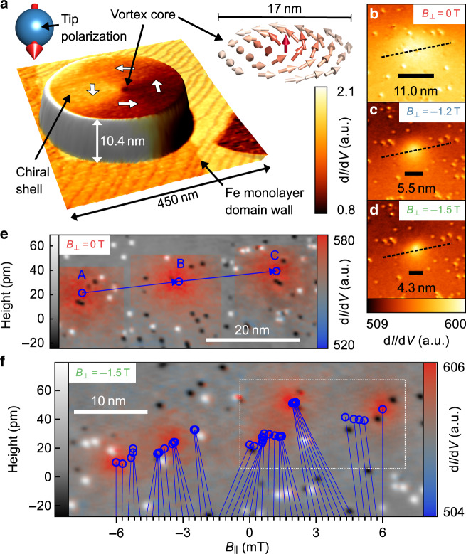
Fig. 1. Vortex core trajectories.
a Superposition of STM topography (3D representation) and simultaneously acquired spin-polarized dI/dV map (color) for an Fe island on W(110), V = −450 mV, I = 0.5 nA. Insets: sketch of deduced tip magnetization vector (left) and spin configuration of the vortex core (right). b–d dI/dV-images of vortex core at identical contrast, identical scale and different B⊥. The labeled scale bars show FWHM of mz extracted by core fitting (“Methods”). e Superposition of topography (brightness) and three semi-transparent dI/dV maps of vortex core (color) after subtracting the signal related to in-plane magnetization (Supplementary Note 3) for mT, mT, and mT at B⊥ = 0 T. Blue vectors connect the deduced vortex core centers (circles) showcasing the linear core motion. f Topography overlaid with vortex core center positions (blue circles) and five selected dI/dV maps (color) for 44 equidistant B∥ steps with ΔB∥ = (136 − 227) μT at B⊥ = −1.5 T. The core center positions are connected to the corresponding B∥ (lower axis) by lines. The dI/dV maps (in-plane magnetization subtracted) correspond to B∥ = −6 mT, −3 mT, 0 mT, 3 mT, 6 mT, V = −2 V, I = 1 nA. A video of the vortex motion including all 45 dI/dV images is available in the supplementary movies. The island size is 255 × 165 × 10 nm3 in b–f and 292 × 210 × 10.4 nm3 in a.

