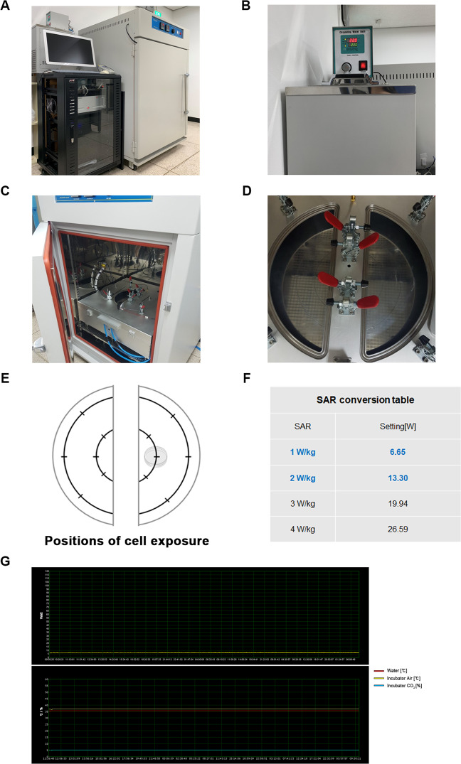
Figure 2.
1.7 GHz LTE RF-EMF cell exposure device and its water cooling system. (A) The 1.7 GHz LTE RF-EMF cell exposure device used. (B) A water cooling system for the incubator to forcibly lower the heated water temperature by 1.7 GHz RF-EMF. (C) The chamber of the incubator with a 1.7 GHz RF-EMF LTE antenna. (D) A plate for cell culture dishes in (C) are located 13.6 cm from the conical antenna in the center of the exposure chamber. (E) A diagram of (D) designating the position of the cell dishes for accurate SAR exposure. (F) The SAR conversion table for this RF-EMF exposure device. SAR values for precise exposure conditions were obtained through engineering calculations. (G) The X-axis in the upper and lower graphs represents the real-time at which the RF-EMF is being exposed to cells. The Y-axis in the upper graph represents the SAR value (Watt) of RF-EMF during the exposure. The Y-axis in the bottom graph shows the temperature of the incubator (yellow line) and the temperature of the refrigerated water-cooling system (red line) of the RF-EMF exposure device during experiment.

