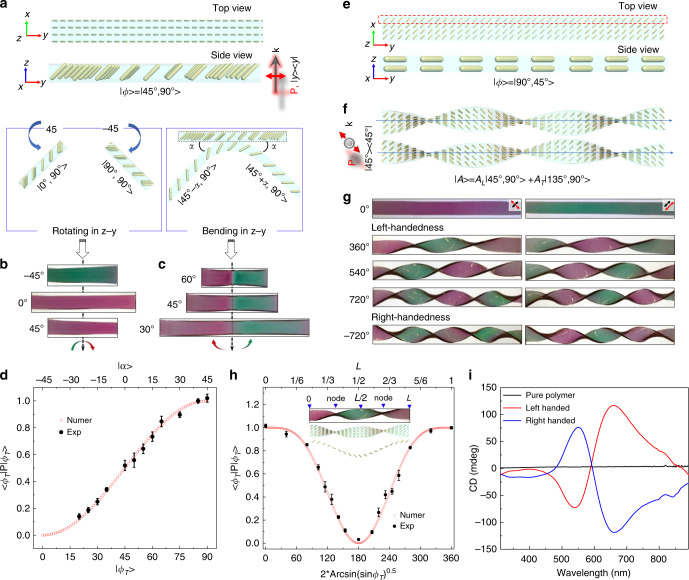
Fig. 4. Motion-active plasmonic films.
a Schematics of the specific arrangement of cAuNRs in the plasmonic film. b Top views of the plasmonic films under different rotation angles. c Top views of the plasmonic films under different bending angles. d The transverse excitation of cAuNRs under different transverse phase angles (ɸT). e Schematics showing the in-plane 45° arrangement of cAuNRs inside the plasmonic film at the top (top) and side view (bottom). f Schematics of left-handed twist (top) and right-handed twist states (bottom). The twisting angle is set at 540°. g Digital images of the plasmonic film at initial (top panel), left-handed (middle panel), and right-handed twisting states (bottom panel). The polarization direction and orientation of cAuNRs are illustrated by red and black arrows, correspondingly. h Dependence of transverse excitation on localized rotation angle and y-coordinates by analyzing the superposition of intensity of transverse and longitudinal resonances to the overall lineshape. Insets: a picture of the twisted plasmonic film and the helical configuration of cAuNRs. i CD spectra of pure polymer and plasmonic films under twisted configuration. Error bars in d and h represent the standard deviations from three experimental measurements.

