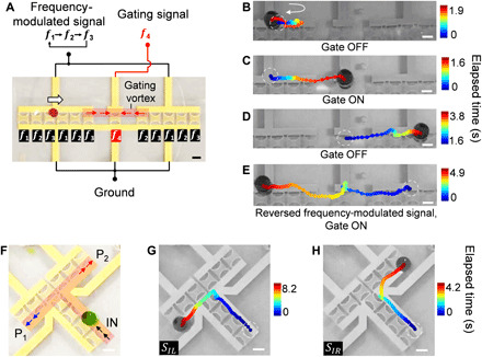
Fig. 6. Active gating and bifurcated routing of droplets via ASVs.

(A) Schematics and images of an active droplet gating device. The red arrows indicate the direction of droplet movement once the gating vortex is formed. The white arrow indicates the default droplet movement direction. (B to E) Time-lapse droplet trajectories when the gating signal (i.e., f4, 41.59 MHz) is (B) OFF and (C to E) ON. (B) The droplet cannot pass the gate and remains in the input channel when the gate is OFF. (C and D) The droplet passes the gate when the gating signal is ON. (E) When the frequency-shifting signal is reversed, the droplet can move from the output channel to the input channel. (F) Schematics and device image of a bifurcated droplet routing unit via ASVs. The red shaded area indicates the location of the ASVs that form the virtual path for droplet transportation. Output port P1, Port1 (left turn); P2, Port2 (right turn). (G and H) Automatic bifurcated droplet routing using different frequency-modulated signals, SIL [left turn (G)] and SIR [right turn (H)]. Scale bars, 500 μm. Photo credits: Peiran Zhang, Duke University.
