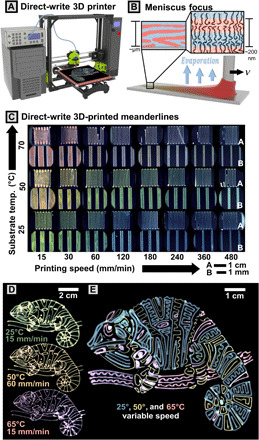
Fig. 2. Direct-write 3D printing scheme.

(A) Render of the printing setup comprising 3D motion axes, pneumatic dispenser, and computer control. (B) Cartoon of molecular assembly during the solution-casting process. Pressure is applied to cause outflow of polymer solution during translation at velocity, v. Microphase separation occurs simultaneously with solvent evaporation to form lamellae. (C) Programmatic variation of optical properties via modulation of printing speed and temperature. Optical microscopy images of printed meanderline patterns on bare silicon are shown in the figure. At each temperature (pair of rows), images at low magnification (inset A) and high magnification (inset B) are shown. (D) Chameleon patterns printed as continuous prints under constant printing conditions (pressure, printing speed, and bed temperature). (E) Complex pattern printed in three layers at three bed temperatures. Print speed was tweaked on the fly to tune line thickness, color, and intensity throughout the print, leading to intended variation seen in the green/blue 25°C lines.
