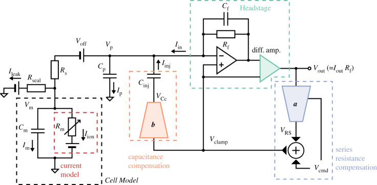
Figure 2.
A more realistic voltage-clamp experiment equivalent circuit. This includes undesired factors such as voltage offset (Voff), series resistance (Rs) between the pipette electrode and the cell, cell capacitance (Cm), pipette capacitance (Cp) and leakage current (Ileak), which can introduce artefacts to the recordings. The circuit also includes the components within a typical amplifier that are designed to compensate the artefacts. The blue (a) and orange (b) components are two idealized multiplying digital-to-analogue converters that control the amount of compensation. We assume that these, and the transimpedance amplifier and differential amplifier (green), are ideal electrical components. Please refer to table 2 for a description of the symbols. (Online version in colour.)

