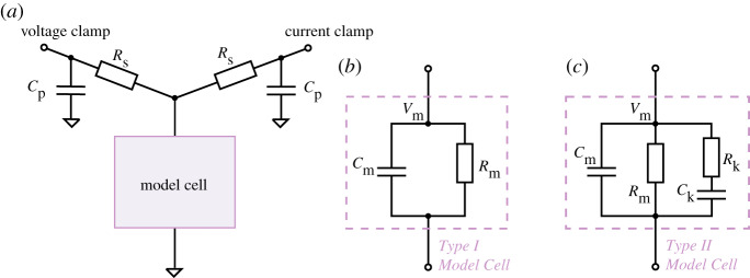
Figure 3.
Circuit diagrams for electrical model cell experiments. (a) A circuit set-up where a model cell is connected to both a voltage-clamp amplifier and a current-clamp amplifier. The voltage-clamp imposes a command voltage, Vcmd, on the model cell and measures the current, Iout, while the current-clamp simultaneously measures its ‘membrane voltage’, Vm. (b) An equivalent circuit of the Type I Model Cell, which is identical to the commercial ‘black box’ model cells (HEKA TESC) under the ‘whole-cell’ mode. (c) An equivalent circuit for the Type II Model Cell. This model cell is designed to exhibit dynamics when stepping to different voltages, with a time constant similar to ionic currents. The circuits were built with discrete electrical components, with Cp = 4.7 pF, Rs = 30 M, Cm = 22 pF, Rm = 500 M, Ck = 1000 pF and Rk = 100 M. (Online version in colour.)

