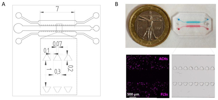
Figure 1.
Design and fabrication of the microfluidic device. (A) Technical drawing of the microfluidic device with dimensions of trapezoidal posts and channels expressed in mm. (B) Top-view of the microfluidic device with ACH (blue) and FLS (red) compartments. The inset shows a stereomicroscope image of the microfluidic chip features. Representative picture showing ACHs and FLSs embedded in fibrin gels after staining.

