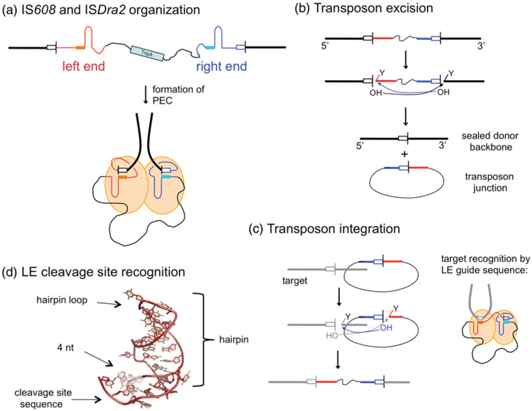
Fig. 4.

ssDNA transposition. (a) One strand of the transposon is shown, with the LE in red and the RE in blue. Both ends have imperfect palindromic sequences located close to the ends which form hairpins (as shown) that are recognized by the TnpA transposase. In the PEC, dimeric TnpA binds one LE and one RE. The cleavage sites (tetra- or pentanucleotides represented by white boxes) are recognized through non-linear base pairing with DNA (shown as solid boxes) at the base of the hairpins; cleavage occurs at the 3′ ends of the cleavage sites. Flanking DNA is represented as a thick black line, and transposon DNA as a thin black line. (b) Transposon excision. Each active site within the dimer cleaves one end. At the LE, this results in a free 3′-OH on flanking DNA and a covalent 5′-phosphotyrosine intermediate on the transposon end (represented by the ‘Y’). At the RE, the reaction with the same polarity results in a free 3′-OH on the transposon end and a covalent 5′-phosphotyrosine intermediate on flanking DNA. When the 3′-OH of one end attacks the phosphotyrosine intermediate of the other, the resulting products are an excised circular transposon junction and a precisely sealed donor backbone. (c) Transposon integration into a target site proceeds through two cleavage steps of the same polarity as for excision. The subsequent attacks of the 3′-OH groups on the 5′-phosphotyrosine intermediates result in an integrated transposon. The target cleavage site is recognized by non-linear base pairing with the DNA at the base of the LE hairpin, as shown for LE cleavage in (a) and (d).
