. 2020 May 27;9:e57887. doi: 10.7554/eLife.57887

Figure 5. A composite model of EMC’s membrane and lumenal domains.

(A) Cross section through the TMD region of the cryo-EM map of EMC (light grey) identifies 13 helix-like densities (dark blue) that define an intramembrane groove (red star) open to the lipid bilayer. Density corresponding to the annular detergent micelle is indicated. (B) Ab initio trRosetta models fitted into cryo-EM density for the EMC membrane domain are shown for EMC1 (wheat), EMC3 (orange), EMC4 (light pink), EMC5 (red), EMC6 (teal), and EMC7 (green). The horizontal density at the membrane-lumen interface termed the ‘crossbar’ is assigned to an amphipathic helix in EMC1. (C) EMC3-3xFLAG constructs containing amber codons (amb.) at the indicated positions were expressed together with an amber suppressor tRNA and cognate aminoacyl-tRNA synthetase that accepts the UV-activated crosslinking amino acid 3'-azibutyl-N-carbamoyl-lysine (AbK). Cells were left untreated or irradiated with UV and analyzed by immunoblotting for EMC3-3xFLAG. A prominent UV-dependent crosslink is seen from position 23 and to a lesser extent, position 26. Native FLAG immunoprecipitation (IP) recovers EMC1 (indicating that EMC3-3xFLAG is incorporated into EMC), which shifts with UV. Denaturing EMC1 IP confirms the crosslinked product contains both EMC1 and EMC3. (D) TMD helices positioned based on docking of ab initio models overlayed with AbK-mediated crosslinks (see Figure 5—figure supplement 3). The positions where AbK was incorporated are shown as spheres, with magenta lines showing the closest point of the target protein in the model. (E) Composite model of the EMC lumenal domain generated by ab initio modelling in trRosetta and real-space refinement in PHENIX. Cryo-EM density has been colored according to subunit identity and the composite lumenal domain model accounts for almost all the lumenal EM density. (F) Cross-section through EMC at the plane of the membrane-lumen interface illustrating that a pore is not evident across the membrane. All EM data visualized in UCSF ChimeraX with EM maps contoured at 0.15 (panel A) and 0.21 (panels B, E, and F) with hide dust setting of 10. Panel D was generated in PyMOL.

Figure 5.

Figure 5—figure supplement 1. Ab initio prediction of EMC subunit structure and flexible fitting using real-space refinement.

Figure 5—figure supplement 1.

Structures were predicted for 9 EMC subunits using the trRosetta server. The best ranked solution for each subunit was then docked into the cryo-EM density and subject to real-space refinement in PHENIX. Number of alignments in the multiple sequence alignment (MSA) is indicated along with the resulting distance contact heat map. The top five ranked models were aligned for the core folds used in EM docking to show modelling confidence. A comparison of the model before and after real space refinement illustrates only subtle changes (green vs grey, RMDS is indicated). Soluble and membrane proteins (EMC2, EMC9, and Sec61a) were modelled and compared to their known structures.
Figure 5—figure supplement 2. Protease-protection analysis of EMC4 topology.

Figure 5—figure supplement 2.

Microsomes isolated from HEK293T cells transfected with an empty vector, EMC4 with an N-terminal 3xHA tag (N-HA-tag), or EMC4 with a C-terminal 3xHA tag (C-HA-tag) were analyzed by a protease-protection assay. Equal aliquots were left untreated, treated with proteinase K (PK), or treated with PK in the presence of detergent (Triton X-100) and analyzed by immunoblotting for the HA tag and the N terminus of calnexin. The N-terminal 3xHA tag was accessible to PK in the absence of detergent, suggesting the N-terminus is exposed to the cytosol. The C-terminal 3xHA tag was protected from PK digestion in the absence, but not presence, of detergent, suggesting that the C-terminus is in the ER lumen. This supports a three TMD model in which the loop between TMD2 and TMD3 is too short to be accessible to PK. A schematic of the results and proposed topology of EMC4 is also shown. In principle, the protease-digestion results are also consistent with a single-spanning topology with the N-terminus facing the cytosol. However, this is unlikely given that all topology prediction algorithms predict at least two TMDs and trRosetta predicts a three helix bundle. Note that the core region in the N-terminal lumenal domain of calnexin is resistant to complete PK digestion.
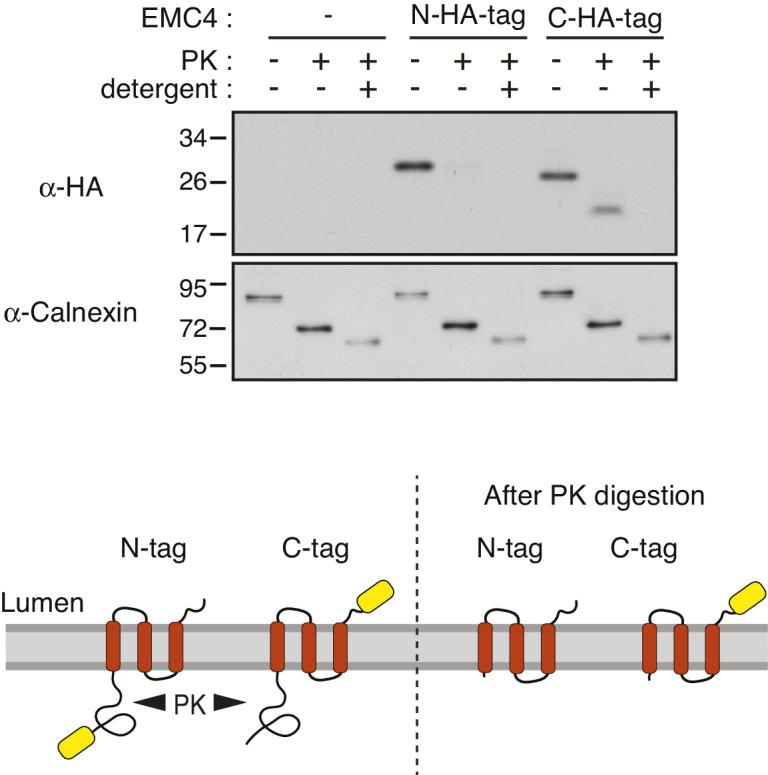
Figure 5—figure supplement 3. Site-specific photocrosslinking between EMC subunits.

Figure 5—figure supplement 3.

(A–E) Experiments similar to that shown in Figure 5C are displayed for the key crosslinks depicted in Figure 5D. In each case, the FLAG-tagged construct indicated on top and containing amber codons (amb.) at the indicated positions was expressed together with an amber suppressor tRNA and cognate aminoacyl-tRNA synthetase that accepts the UV-activated crosslinking amino acid 3'-azibutyl-N-carbamoyl-lysine (AbK). Cells were left untreated or irradiated with UV and analyzed by immunoblotting for the FLAG epitope in total lysate as indicated. In panels A, C, D, and E, lysates were subjected to native FLAG immunoprecipitation (IP) and immunoblotted for the indicated targets. In panel B, lysates were subjected to denaturing EMC4 IP and blotted for the FLAG tag and EMC4 as indicated. (F) Summary of the observed crosslinks and where the primary data are displayed in the figure. Note that various positions from which crosslinks to an particular target was not observed are not shown for brevity.
Figure 5—figure supplement 4. Provisional assignment of non-EMC2•EMC9 cytosolic density.

Figure 5—figure supplement 4.

Semi-automated segmentation in UCSF chimera revealed regions of density in the cytosolic domain of the cryo-EM map of the EMC which are not accounted for by the EMC2•EMC9 heterodimer (translucent densities). Based on the position and connectivity to the respective TMDs in the membrane portions of this density were provisionally assigned to EMC1 (brown) and the N-terminus of EMC6 (teal) which is proposed to form a ‘placeholder’ in the cytosolic substrate binding pocket. A predicted three-helix bundle formed from a coiled-coil between TMD1 and TMD2 of EMC3 interacting with a helix in EMC3’s C-terminal tail was fit into a similarly shaped and sized density. In this fitted model, Q71 of EMC3 is surface-exposed and near where the N-terminal tail of EMC4 might reside. AbK incorporated at Q71 shows a UV-dependent crosslink to EMC4 (Figure 5—figure supplement 3), consistent with our assignments. The remaining density is continuous with the C-terminal helix in this three-helix bundle and was therefore provisionally assigned to the rest of EMC3’s C-terminal tail.
Figure 5—figure supplement 5. Views of the composite EMC model.

Figure 5—figure supplement 5.

Shown are multiple views of the composite EMC model which contains all nine EMC subunits. Where possible, the same color scheme as used throughout the main figures was employed with EMC1 (tan), EMC2 (light grey), EMC3 (orange), EMC4 (dark pink), EMC5 (red), EMC6 (teal), EMC7 (lime), EMC9 (dark grey), and EMC10 (purple).