
Figure 2.
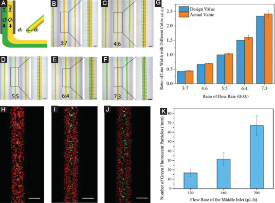
Printing of heterogeneous filaments by changing flow rate ration of different solutions in the microfluidic printhead. (A) Schematic for the deposition of heterogeneous filaments from the microfluidic printhead. (B, C, D, E, F) Microscopic images of heterogeneous filaments printed by changing the flow rate ratio of two solutions. Scale bar=200 µm. (G) Quantification of the composition distribution of two inks in the printed filaments. (H, I, J) Fluorescent images of the heterogeneous filaments printed through the three inlets with different flow rate of middle inlet. Scale bar=200 µm. (K) Quantification of the number of green fluorescent particles at different flow rate of the middle inlet.