Fig. 5.

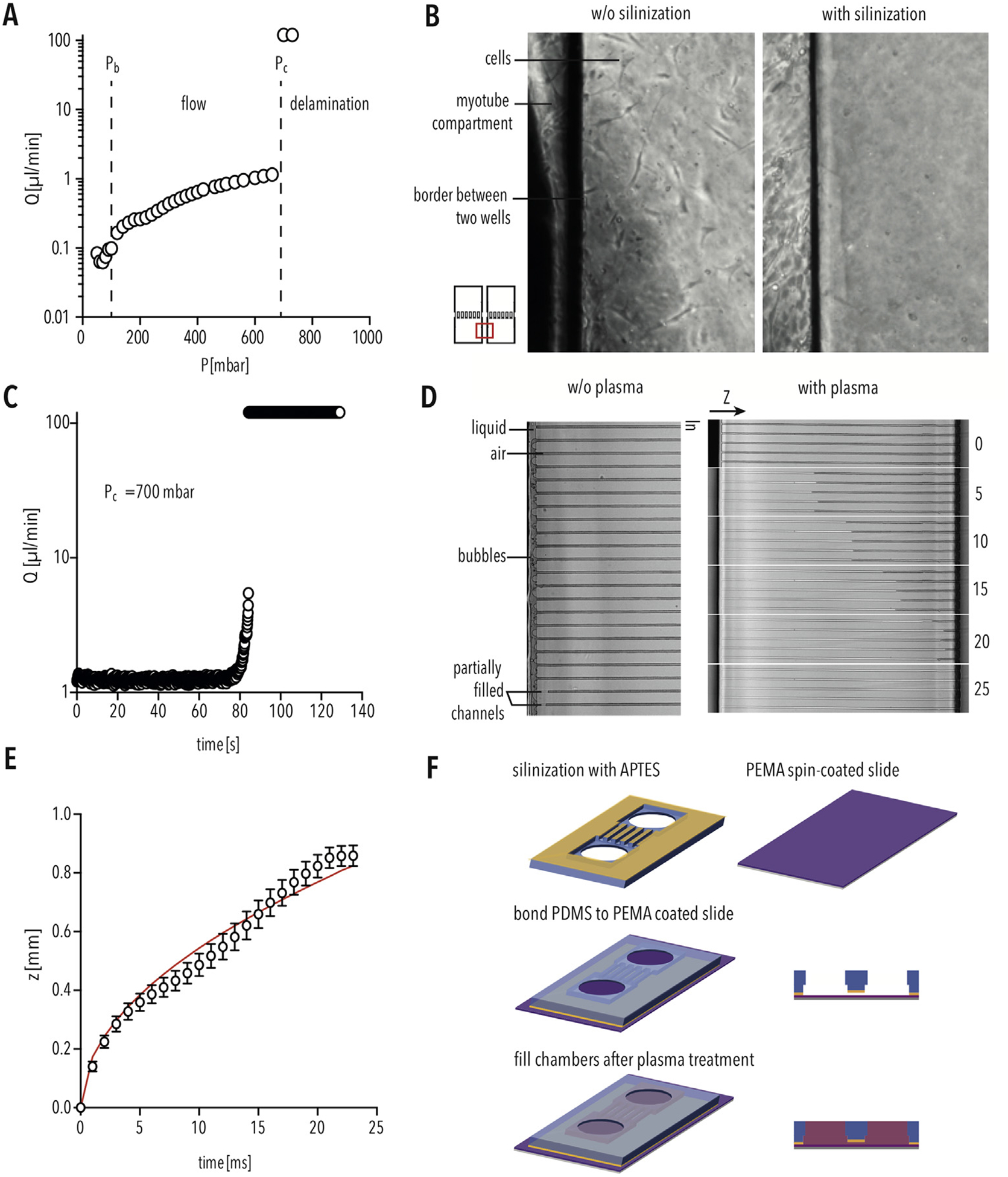
PEMA MFP device preparation using PDMS silanization and plasma treatment (A) Flowrate (μl/min) inside the PEMA-PDMS device corresponding to the applied pressure (mbar). Pb indicates capillarity back-pressure, the pressure required to fill the well. Pc indicates the critical pressure, the pressure at which the PDMS delaminates from the PEMA-coated cover slip. (B) Silanization of PDMS results in sufficient bonding to prevent cell growth between the compartments. (C) Flowrate (μl/min) inside the PEMA-PDMS device over the time period (s) at constant critical pressure (Pc) of 700 mbar. (D) Bright-field image of filling the micro-channels without (left) and with (right) air plasma treatment. (E) Covered length (z) for water penetration inside the air plasma treated micro-channels over a time period (ms). The solid red line is the best fit curve by z = A∙(time)0.5 [24]. Bars indicate SD. (F) Schematic of PEMA MFP preparation. (For interpretation of the references to colour in this figure legend, the reader is referred to the Web version of this article.)
