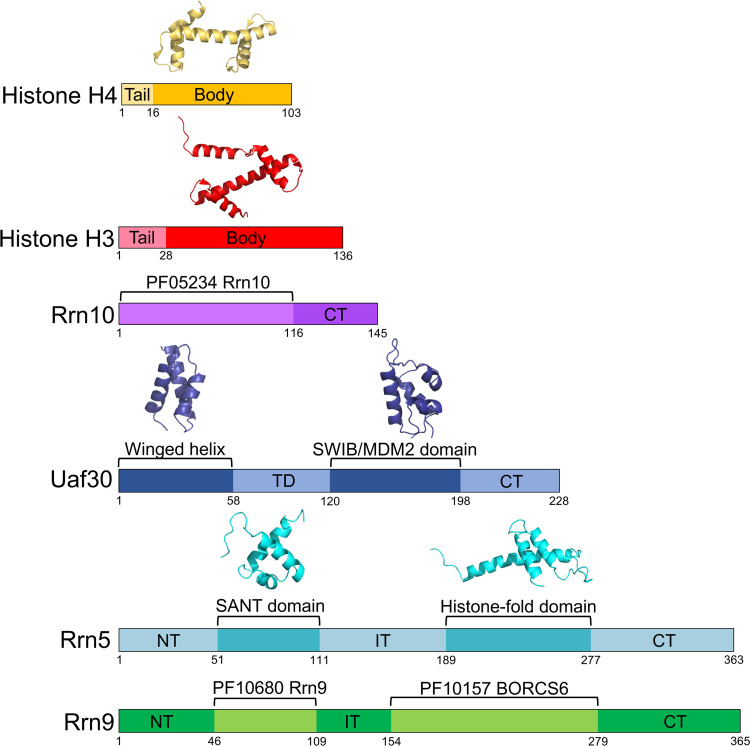
FIG 1.
Predicted domain organization of UAF subunits. Domain maps of each UAF subunit are shown and colored accordingly. Predicted functional and/or structural domains are labeled. Structural models of available domains are depicted above the domain maps. NT, N terminal; CT, C terminal; TD, tethering domain; ID, internal domain. Domain boundaries are denoted with residue numbers below the maps.

