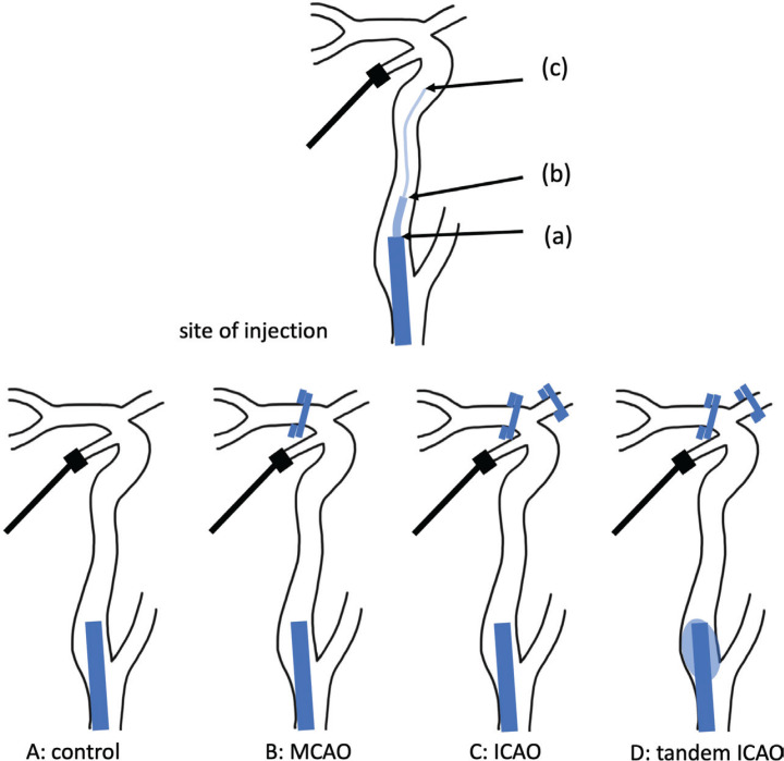
Fig. 2.
Schematic view of the vascular model. The upper illustration shows the site of injection. A pressure-transducer is placed at the terminal internal carotid artery (ICA). (a) A 9-Fr balloon-guiding catheter is placed at the origin of the right ICA. (b) A 4-Fr inner catheter is placed at the cervical ICA via a 9-Fr balloon-guiding catheter. (c) A microcatheter is placed at the siphon of the ICA via a 4-Fr inner catheter and a 9-Fr balloon-guiding catheter. The lower illustrations show the various models. (A) Control model in which each vessel is opened. (B) MCAO model in which the MCA is occluded by a clip. (C) ICAO model in which both the MCA and ACA are occluded. (D) Tandem ICAO model in which both the middle cerebral artery and the anterior cerebral artery are occluded by a clip and the origin of the ICA is wedged by the balloon.

