Figure 5.

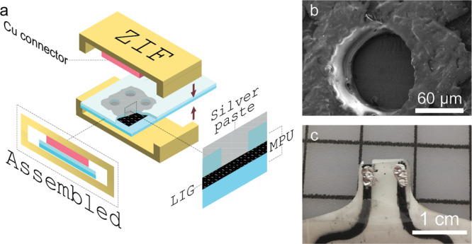
(a) VIA scheme with ZIF-connector for wiring, (b) SEM image of laser-cut holes in the top layer of MPU, and (c) photo of a finished connector with silver ink-filled VIAs.

(a) VIA scheme with ZIF-connector for wiring, (b) SEM image of laser-cut holes in the top layer of MPU, and (c) photo of a finished connector with silver ink-filled VIAs.