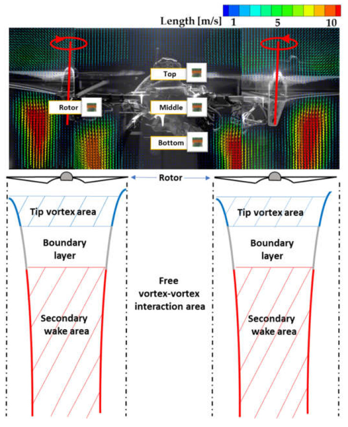
Figure 7.
Vortex phenomena caused by the differing flow rates in two adjacent sections under the rotor blades. Although the tip vortex area and boundary layer seem to be fairly thick from the illustration, they are actually very thin, and the secondary wakes constitute most of the flow profiles. Also, based on the present PIV measurements, we selected four possible sensor locations (Rotor, Top, Middle and Bottom) on a drone.

