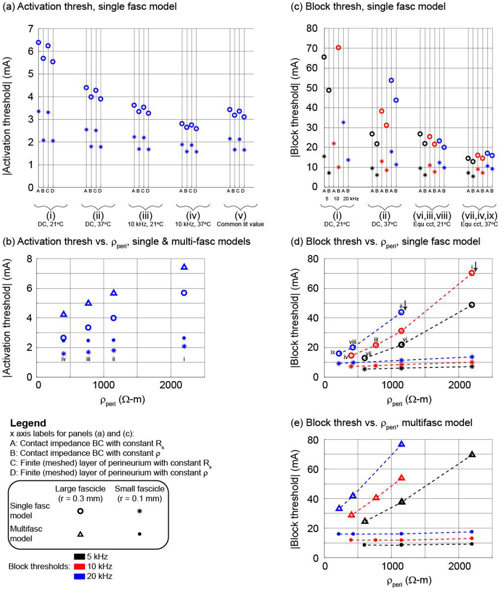
Figure 4.

Using the bipolar circumferential cuff and a 2 μm axon in the centre of the middle fascicle (see illustration of methods in Figure 2), thresholds for activation ((a) and (b)) and block ((c) to (e)) with different representations of the perineurium (x axis labels A to D) and estimates of perineurium resistivity (i to ix; see Table 2). Panels (b), (d), and (e) show the Method B data (constant ρ). Panels (a), (c), and (d) show thresholds for the single fascicle model. Panel (b) shows thresholds for the single fascicle and multifascicular nerve models. Panel (e) shows thresholds for the multifascicular model; the labels i to viii in panel (d) also apply to panel (e). Results for other electrode designs, fibre diameters, fascicles, and axon locations are provided in Supplement D.
