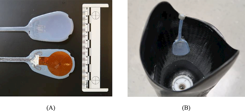
FIGURE 2A,B.

WAFER sensor. (A) The WAFER antenna, thermistor, capacitor, and lead wires were affixed to the back surface of the plastic shell (lower part of image). The inside surface of the shell (upper part of image) faced the liner. (B) Top-view of socket showing WAFER sensor positioned within a socket.
