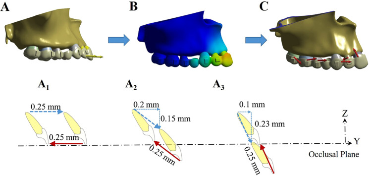
Figure 2.
Loading method of the finite element model to simulate incisor retraction with a clear aligner. The incisors were first displaced in the opposite direction of retraction (A). This led to the deformation of the aligner matching the dentition (B). The forces generated by the aligner on each tooth were then calculated and finally loaded back on the corresponding tooth in the reverse direction (C). Three retraction protocols were designed with different amounts of retraction and intrusion with the same total amount of movement of 0.25 mm (A1, A2 and A3). Dashed arrows indicate the vectors of incisor displacement that activate the aligner. Solid arrows indicate the vectors of the designed incisor retraction.

