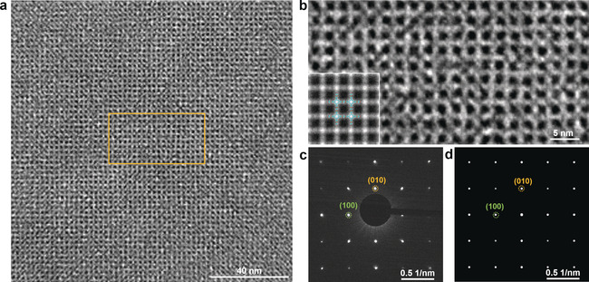
Figure 3.

a) HR‐TEM image of 2D BECOF‐PP film that shows a long‐range ordered 2D networks of square‐patterned pores. b) Enlarged HR‐TEM image from the region in image a (yellow square). Inset is lattice‐averaged image calculated from the DFT. c) Experimental and d) simulated electron‐diffraction patterns, the green and yellow circles indicate the (100) and (010) planes, respectively.
