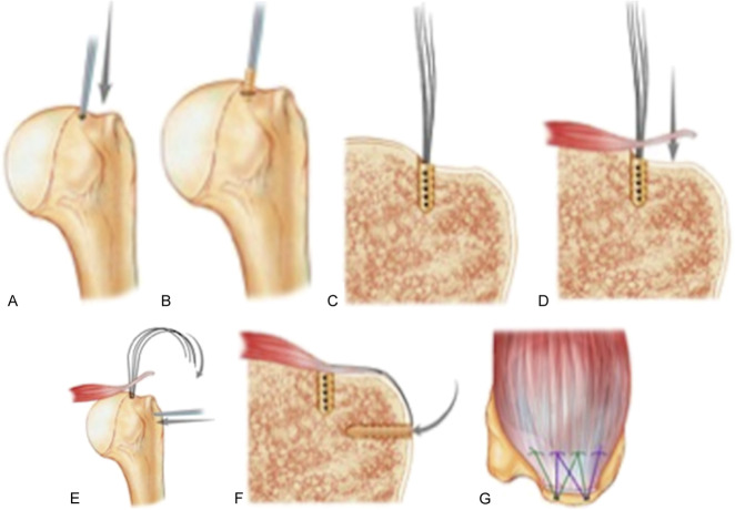
Fig. 3A-G These images illustrate the surgical steps of the typical anchored (transosseous equivalent) approach to repair of a torn rotator cuff. (A) A bone punch was used at the desired anchor site in the greater tuberosity (arrow), and (B) an anchor was inserted into the pilot hole. (C) This image is a coronal cross-section of the anchor in the tuberosity. (D) These images show a coronal cross-section of cuff reduction in the greater tuberosity (arrow), and (E) a bone punch used to insert a lateral anchor in the greater tuberosity (straight arrow shows direction of punch, and curved arrow shows direction of suture passage). (F) This image is a coronal cross-section of the anchored transosseous equivalent cuff repair after a lateral row anchor was placed (arrow). (G) This image is a superior view of anchored transosseous equivalent cuff repair. Illustration: Tim Phelps, MS, FAMI, © (2016) JHU AAM Department of Art as Applied to Medicine, The Johns Hopkins University School of Medicine.

An official website of the United States government
Here's how you know
Official websites use .gov
A
.gov website belongs to an official
government organization in the United States.
Secure .gov websites use HTTPS
A lock (
) or https:// means you've safely
connected to the .gov website. Share sensitive
information only on official, secure websites.
