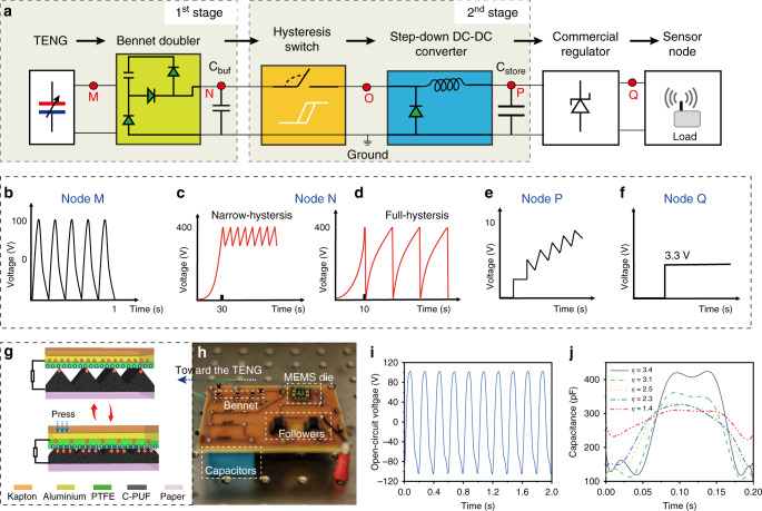
Fig. 1. Schematic and electrical states of the conditioning circuit.
a Diagram of the conditioning system. Shapes and orders of magnitude of the voltages (b) generated by the triboelectric nanogenerator (TENG) used in the experiments, across the buffer capacitor with a narrow-hysteresis switch (c) or a full-hysteresis switch (d), e across Cstore, f at the output of the regulator. g Schematic and operation principle of the TENG44 constructed with Kapton, Polytetrafluoroethylene (PTFE), Aluminium, conductive polyurethane foam (C-PUF) and paper. h The printed-circuit-board of the circuit. i Open circuit voltage of the TENG. j Capacitance variations of the TENG under different tapping forces, from 2 N to 10 N with 2 N per step, corresponding to different capacitance variations (η). Source data are provided as a Source data file.

