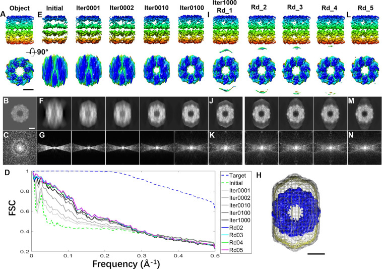
Figure 3.
The missing-wedge correction under a large mask on a simulated 3D map reconstructed from the noise-free ± 15° tilt series of GroEL (A) A 3D object shown from two perpendicular views. The object was generated from the crystal structure of GroEL, and the ideal 3D map was constructed from the tilt series of the noise-free 2D projections of the object from tilt angles in a range of ±90° in steps of 1.5°, while the initial 3D map was reconstructed from angles of ±15°. (B) The projection of the object on the X-Z plane and (C) its Fourier transform. (D) The ideal FSC curve was computed between the object and the ideal 3D map, as shown by the blue dashed line. The other curves were computed between the object and iterative maps. (E) The initial 3D map and iterative 3D maps, shown from perpendicular views. (F,G) Their corresponding projections on the X-Z plane, and the corresponding Fourier transforms. (H) A large mask corresponding to 3.8 times the molecular weight of GroEL was generated from the low-pass-filtered initial 3D map (~40 Å, shown in the mesh; the object is shown in blue). (I) The final 3D maps after each round (containing 1,000 cycles of iteration) of missing-wedge correction. The maps of round 1 (Rd_1) and rounds 2–4 are shown from perpendicular views, as well as (J) their projections on the X-Z plane and (K) the Fourier transforms. (L–N) The final 3D map after round 5 is shown from perpendicular views, compared to its projection on the X-Z plane and the Fourier transform. All 3D maps underwent low-pass filtering to 8 Å. Scale bars: 50 nm.

