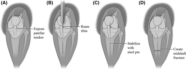
Figure 2.

Anatomic illustrations depicting the stabilized mid‐shaft tibia fracture model. Figure modified from Bratton, et al 52 A. Illustration showing the left hind stifle of C57BL/6 mouse. (A) small midline skin incision was made distal to the knee. Skin is manually adjusted to expose the knee joint and patellar tendon. (B) A 27‐gauge needle is slide behind the patellar tendon and inserted into the tibial plateau. Using a twisting motion, the needle reams through into the intramedullary canal. (C) The needle is removed and replaced with a steel insect pin that is inserted down the length of the tibia. (D) The insect pin is trimmed flushed with the tibia plateau. The skin incision is then manually adjusted to reveal the midshaft of the tibia. Using angled bone cutters, a complete fracture is made through both cortices of the diaphyseal bone while not damaging the intramedullary stabilizing pin. The incision is then suture closed after verifying the injury is complete and properly stabilized
