Figure S6.
Controls Related to Propagator Analysis, Related to Figures 5C–5F
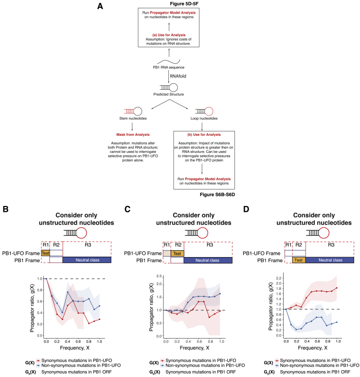
(A) Schematic of analysis steps taken to quantify selection occurring on synonymous and non-synonymous mutations in the PB1-UFO ORF. Propagator model analyses were done by either not taking (Figure 5B and 5D) or taking the RNA structure of IAV PB1 segment into account (Figures 5C–5E).
(B) Frequency propagator ratios of the indicated classes of mutations occurring in PB1-UFO relative to the PB1 open reading frame of H3N2 viruses. The region used to calculate the test class ratio (G(X)) is indicated in yellow, and the region used to calculate the neutral class ratio (G0(X)) is indicated in blue in the top schematic. Here, the test class is the region of the PB1-UFO ORF that overlaps only with the virally-encoded 5′UTR; the neutral class consists of synonymous mutations in the PB1 ORF that do not overlap with PB1-UFO. Only nucleotides within predicted loop regions (i.e., non-pairing) positions were considered. Error bars indicate sampling uncertainties. : negative selection, : weak/heterogeneous selection; : positive selection; see also Figure 5C)
(C) Frequency propagator ratios, as in (B), but with the test class comprising the C-terminal region of the PB1-UFO ORF.
(D) Frequency propagator ratios, as in (B), but with the test class comprising the region in the main PB1 ORF overlapping the PB1-UFO reading frame.

