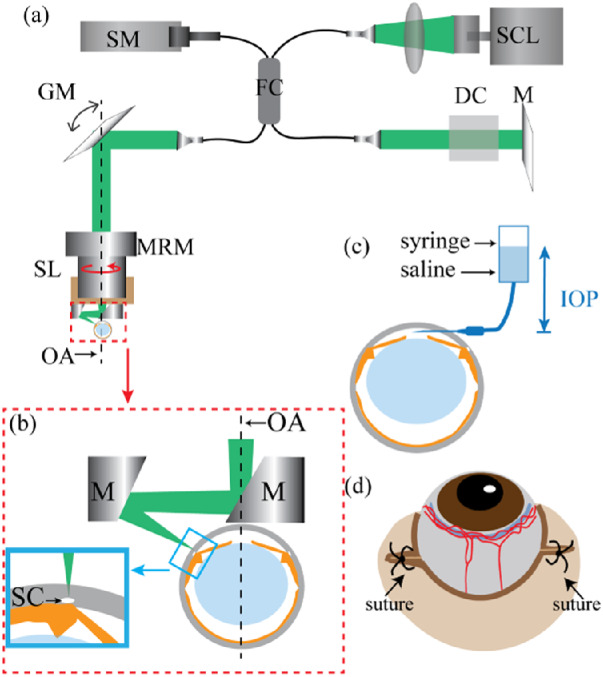
Figure 1.

(a) Schematic of the vis-OCT system. DC, dispersion compensation; FC, fiber coupler; GM, galvanometer mirrors; M, mirror; MRM, motorized rotational mount; SCL, supercontinuum light source; SL, scan lens; SM, spectrometer; OA, optical axis of the eye, which is also the axis of rotation of the motorized rotational mount. (b) Detailed illustration of the components being highlighted by the red dashed box in panel (a). M, mirror; OA, optical axis; SC, Schlemm's canal. The incident light reflects off both the mirrors after the SL, such that it is angled perpendicularly to the surface of the eye at SC, as shown in the blue inset. (c) Illustration of the cannulation of the anterior chamber with an open syringe filled with physiologic saline, whose height can be adjusted to set IOP levels in the mouse eye. (d) Illustration of sutures to cause blood reflux into SC.
