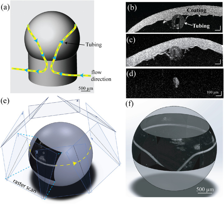
Figure 2.
(a) Schematic of the 3D-printed phantom eyeball, with tube inset into groove shown in yellow. Direction of the Intralipid flow is shown with the blue dashed line. (b) Vis-OCT B-scan image of the phantom eyeball without flowing Intralipid. (c) Vis-OCT B-scan image of the phantom eyeball with flow Intralipid. (d) Vis-OCTA B-scan image of the phantom eyeball with flowing Intralipid. (e) Geometry of how the eight raster scans are montaged onto a sphere. (f) 3D visualization of the montaged image of the phantom eyeball.

