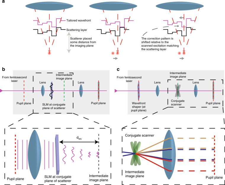
Fig. 1. Pupil vs conjugate wavefront correction and z-scanless implementation.
a In adaptive optics/scattering compensation scanning microscopy, a correction pattern is applied to the excitation beam, which undoes the scattering induced by the inhomogeneous medium between the objective and the imaging plane (left). If the dominant scattering layer is positioned at a considerable distance away from the imaging plane compared with the wavelength, the correction pattern ends up getting scanned against the layer itself (middle). Although part of the information for the compensation is still there, no efficient scattering compensation is achieved. We can compensate for this effect by descanning the correction pattern against the scattering layer (right). b One approach to overcoming this problem is to directly image the wavefront shaper at the position of the dominant scattering layer between the imaging and the pupil plane. However, in this case, correcting for different distances of the scattering layer to the imaging plane requires the physical displacement of the wavefront shaper within the optical path. c Alternatively, we achieve the proper conjugate wavefront correction by actively scanning the correction pattern against the pupil of the optical system by a 2D scanning mirror introduced in the intermediate imaging plane. Correcting for different distances between the scattering layer and the imaging plane is achieved by changing the relative displacement of the correction pattern against the pupil aperture.

