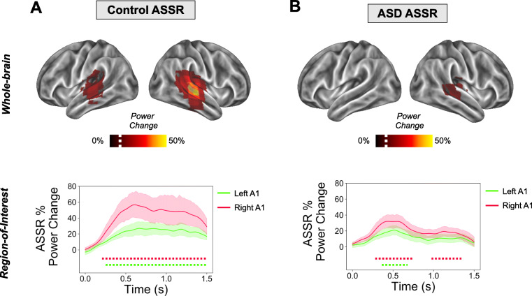
Fig. 3.
ASSR power analysis. Top panels (a, b): ASSR beamformer localization. The percentage change in ASSR power (35-45 Hz) is presented on a 3D cortical mesh, thresholded at values greater than 10% (white dotted line on colour scale) for illustrative purposes (for unthresholded images, see Supporting Figure 3), separately for control (a) and ASD (b) groups. Bottom panels (a, b): ASSR in regions of interest (ROIs). ROIs were defined in left and right A1 (see Supporting Figure 1) and ASSR oscillatory power was calculated between 35-45 Hz. The time-period 0-1.5 s post-clicktrain onset was statistically compared with a 1.5 s baseline period. Data are plotted separately for (a) the control group and (b) the ASD group. Dotted lines under the graph indicate times passing a p < 0.05 threshold (two-tailed) compared to baseline, with different colours corresponding to right A1 (red) and left A1 (green). ASSR, auditory steady state response

