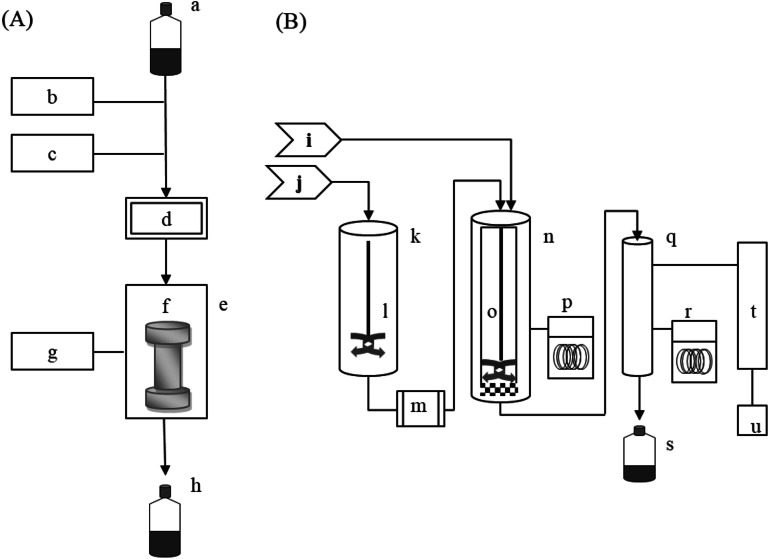
Figure 1.
Schematic diagrams of the laboratory-scale (A) and pilot-scale (B) SWE systems, showing the solvent bottle (a), pump (b), nitrogen gas (c), pressure transducer (d), oven (e), extraction cell (f), temperature controller (g), collection bottle (h), nitrogen gas (i), water supply (j), preheater (k), stirring bar (l), pump (m), extractor (n), stirring bar (o), cooling system (p), collector (q), cooling system (r), collection bottle (s), condenser (t), and computer control system (u).

