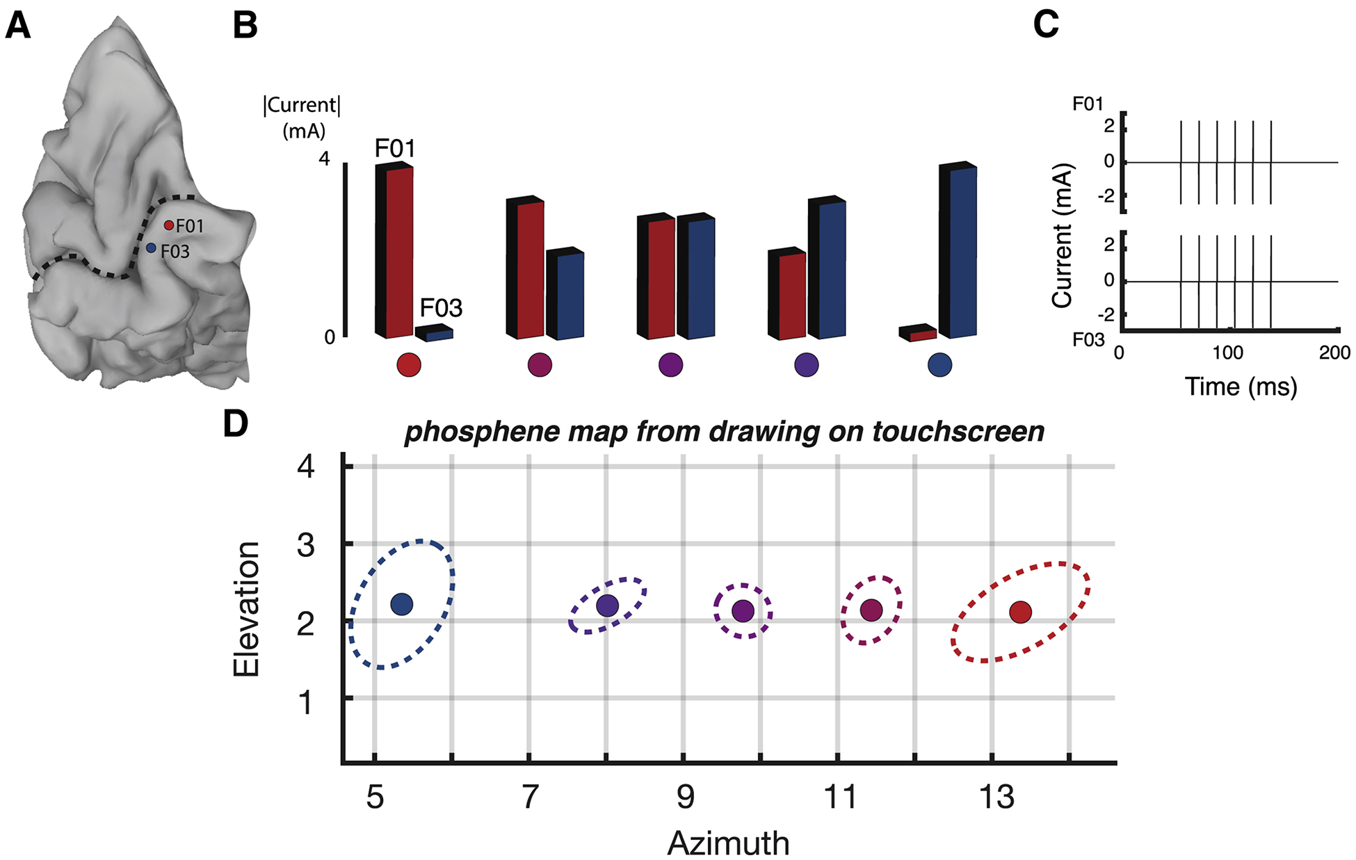
Figure 2. Effectiveness of current steering in a blind participant.

(A) A medial view of a cortical surface model of the participant’s occipital lobe (dashed line indicates calcarine sulcus). Two subdural electrodes are shown as a red and a blue disc (labeled F01 and F03). (B) Current steering was implemented by delivering varying amount of current to the two electrodes. In the first condition, maximum current was delivered to electrode F01 and no current was delivered to electrode F03; in successive conditions, the amount of current to F01 was decreased and the amount of current delivered to F03 was increased, until in the fifth condition, no current was delivered to F01 and maximal current was delivered to F03. Colored circles underneath each condition correspond to phosphene locations in (D). (C) In each condition, current was delivered in a single 100 ms pulse train with 6 pulses per train (pulse frequency of 60 Hz). The pulse train for the third stimulation condition in (B) is shown, with equivalent current amplitudes for F01 and F03. For other conditions, the current amplitude delivered to the electrodes differed, but the timing of the pulse trains was identical. (D) The participant used a touch screen to report the location of the visual percept resulting from each stimulation condition. Ten trials of each condition were performed. The colored circle shows the average location of all reports for that condition, the dashed line shows the 95% spatial confidence interval fit with an ellipse. Colors of each circle and dashed line correspond to condition colors shown in (B).
