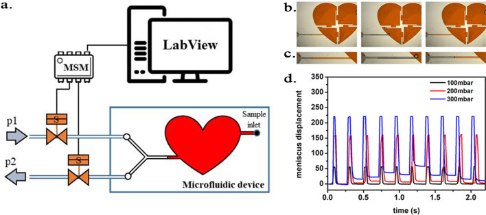
Figure 12. Scheme of the experimental setup.
(a) Scheme of the experimental setup with the heart-shaped polydimethylsiloxane (PDMS) microfluidic device. (b) time-sequence snapshots of the device in operations. From left to right: the device is filled with liquid and is at rest (for better visualisation we used here red-dyed water instead of the transparent protein solution). The microchannel connecting the pressure system to the microfluidic chamber is filled halfway. Applying high pressure (valve # one open) pushes the liquid meniscus towards the chamber. Closing valve # one and opening valve # 2 (low pressure) the liquid meniscus pulls back (even further than its original position). (c) Close-up of the moving liquid meniscus, (d) oscillation profile generated from the position of the liquid meniscus in the microchannel as a function of time for various pressure differences Δp=p1 p2.

