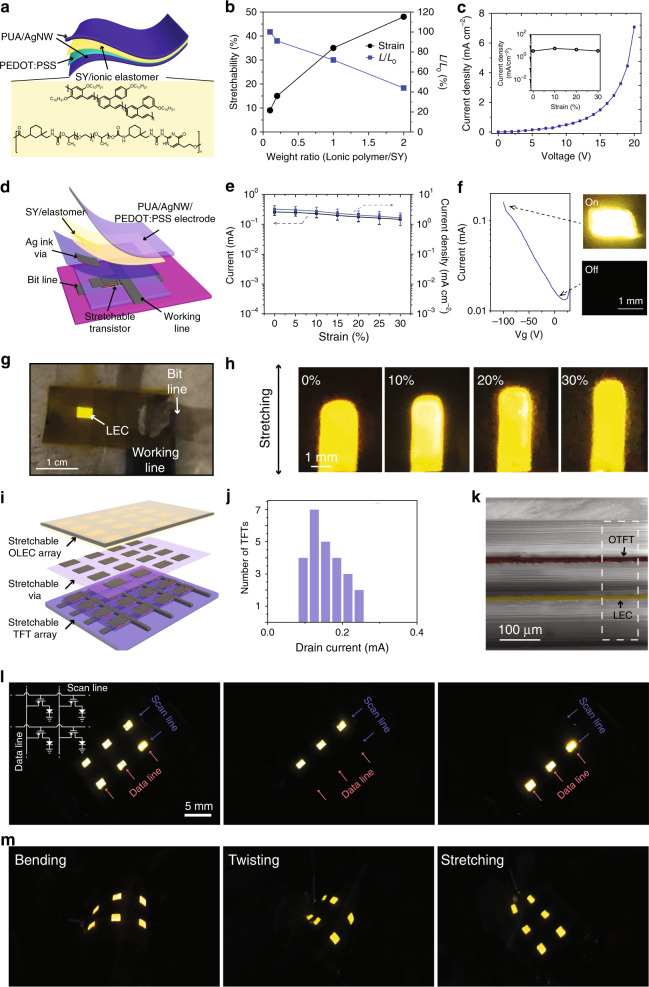
Fig. 4. Fully stretchable AMOLEC array.
a Schematic of the stretchable light-emitting electrochemical cell (LEC). Yellow highlighted schematics show the molecular structure of stretchable ion-conducting polymer and super yellow (SY) used to enable the stretchable, tissue-level soft LEC. b Strain tolerance and light-emitting intensity ratio (light-emitting intensity/initial light-emitting intensity, L/L0) of LEC to the different weight ratios of ionic polymer to SY. c Representative curve of current density as a function of the voltage of the stretchable LEC with 1:1 weight ratio of stretchable polymer: SY. It shows a stable current density as a function of strain (inset). The active area of the device is 2 × 3 mm2. The “on” state of the LEC is defined as current density above 2 mA/cm2 as chosen by curves in c. d Schematic 3D layout of individual stretchable LEC pixel driven by a stretchable OTFT. e Drain current and the corresponding current density of the fully stretchable OTFT subjected to strains from 0 to 30%. Values are mean ± S.D. f The on-off-current from the transistor controlled by the gate voltage and the representative images of LEC at “off” and “on” states. g Photographic image of a stretchable LEC pixel turned-on by the vertically integrated stretchable transistor. h Photographic images of a single LEC pixel subjected to different strains. i Schematic of the vertical integrated active matrix and LEC array. j The histogram of drain-currents from a typical stretchable OTFT active matrix. k A SEM cross-sectional image of an AMOLEC device stack after subjected to 30% strain and released. The false colour highlights the active layer of OTFT (red) and LEC (yellow), respectively. l Photographic images of the AMOLEC skin display pixels with different columns being selectively turned on. m Photographic images of AMOLEC skin display pixels subjected to both bending, twisting and stretching.

