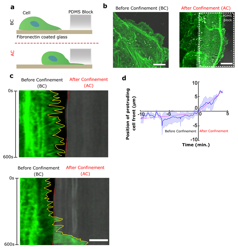
Extended Data Figure 4. Cell confinement induces large protrusive activity and high speed of cellular protrusions at the cell front.
a, Schematics explaining the experimental set-up to confine front cell extensions. b, Representative images of actin-GFP cells on fibronectin coated glass substrates. Before confinement (BC) shows cells with a free leading edge and protruding activity. After confinement (AC) shows cells whose leading edges are confined underneath the confining PDMS block (scale bar: 10 μm). c, Kymograph of the cell front before (top) and after confinement (after) (scale bar: 5 μm). d, Cell edge position over time before and after confinement. Negative time correspond to the front edge position before confinement and positive time after confinement (n=10). The slope of curve (dashed magenta line) indicates the velocity of cell protrusions before (0.27 μm/min) and after confinement (1.58 μm/min), respectively. All error bars indicated are standard deviations.

