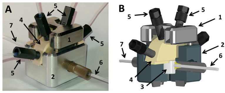
Figure 6.
(A) Droplet generator (Figure 3B); (B) scheme of the droplet generator with sectional cut. (1) supporting frame top; (2) supporting frame bottom; (3) exchangeable PTFE inlet for droplet generation; (4) fluid manifold routing up to four different media streams into the PTFE droplet generator; (5) fluid connector for media supply; (6) fluid port for the carrier medium inlet; (7) fluid port outlet for the droplet sequence.

