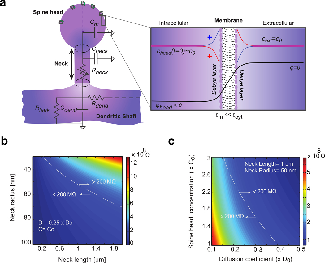
Figure 1: Modeling the dendritic spine geometry and its electro-diffusional properties.

a) Spine head contains ion channels. It is connected to the parent dendrite with a thin cylindrical neck. Membrane is modeled as an impermeable dielectric with small electrical permittivity compared to cytoplasm (). At resting state, the spine head is polarized with negative electrical potential ∈m ≪ ∈m compared to external potential Ion concentration chead(t) also varies compared to bulk concentration c0. Bulk is electroneutral except for a thin boundary layer near the membrane- i.e. the Debye layer (inset), where positive (red line) and negative (blue line) ion concentrations differ due to local variation of the electrical potential (black line). Most of the electrical potential drops through the poorly conducting cell membrane. Equivalent circuit describing the dendritic spine electrostatics is represented: Cm denotes the capacitance of the head membrane, Cneck and Rneck denote the membrane capacitance and the longitudinal cytoplasmic resistance of the spine neck. Cdend and Rdend denote the membrane and resistance of the dendrite. An additional membrane resistance Rleak models the ion leaks through the dendrite membrane. All of which combine to determine the voltage dynamics inside the spine head. b) Geometrical determinants of passive spine neck resistance (ion diffusion coefficient and concentration are respectively fixed to and c0 = 150 mM). c) Physiological determinants of spine neck resistance (neck length and radius are respectively fixed to L = 1 μm and r0 = 50 mn).
