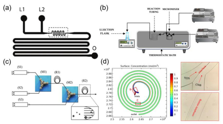
Figure 1.
(a) Schematic illustration of microfluidic channels containing two liquid inlets (L1 and L2) and one outlet (O) for the preparation of silica nanoparticles (reproduced from [23], with permission from the American Chemical Society, 2004). (b) Experimental setup for the continuous synthesis of nanoparticle (reproduced from [24], with permission from the Elsevier, 2011). (c) Schematic diagram of microfluidic reactor systems with (S1) syringe for tetramethoxysilane (TMOS), (S2) syringe for 1 mM HCl, (S3) syringe for polyethylenimine (PEI) polymer in Tris–HCl buffer solution, (M1) and (M2) PEEK Y-shape mixers, (R1) reaction tube for hydrolysis, as well as (R2) reaction tube for silica precipitation (reproduced from [25], with permission from Elsevier, 2011). (d) Simulation and experimental results of reactants mixing in the spiral microchannel (reproduced from [26], with permission from Springer Nature, 2017).

