
Figure 3.
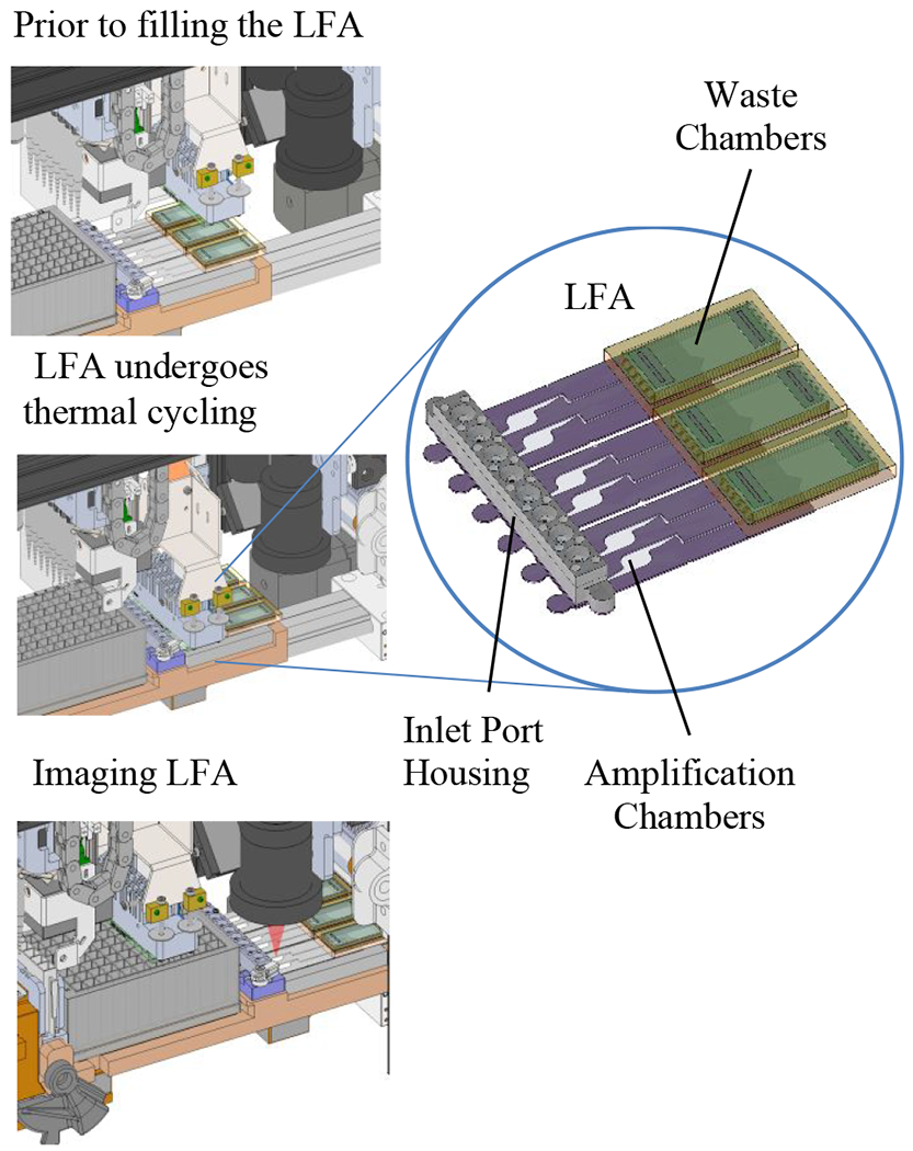
Illustration of the LFA on the system with the thermal cycler in the (1) “up” (disengaged) position, (2) in the “down” (engaged) position, and (3) with the imager capable of individually imaging and analyzing each array of gel elements.
Official websites use .gov
A
.gov website belongs to an official
government organization in the United States.
Secure .gov websites use HTTPS
A lock (
) or https:// means you've safely
connected to the .gov website. Share sensitive
information only on official, secure websites.
Illustration of the LFA on the system with the thermal cycler in the (1) “up” (disengaged) position, (2) in the “down” (engaged) position, and (3) with the imager capable of individually imaging and analyzing each array of gel elements.