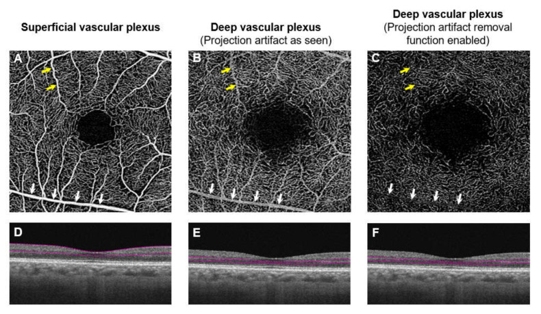
Figure 10.
Angiographic images and projection artifacts. (A–C) are different en face capillary plexus and (D–F) are their corresponding B-scan images of the same eye. The superficial capillary plexus is shown in A and deep capillary plexus is shown in (B,C). When the segmentation section is lowered to include the region around the inner nuclear layer and outer plexiform layer, the deep capillary plexus should be seen. However, the vascular pattern seems similar to the superficial capillary plexus. Note the superficial vessels seen in the angiographic image (yellow and white arrows; (A,B). The superficial vessels are seen because of a projection image. When the projection removal algorithm is enabled, it removes most of the projection image from the superficial capillary plexus. Although smaller superficial vessels are no longer visible (yellow arrows); (C) larger superficial vessels still persist (white arrows; C).

