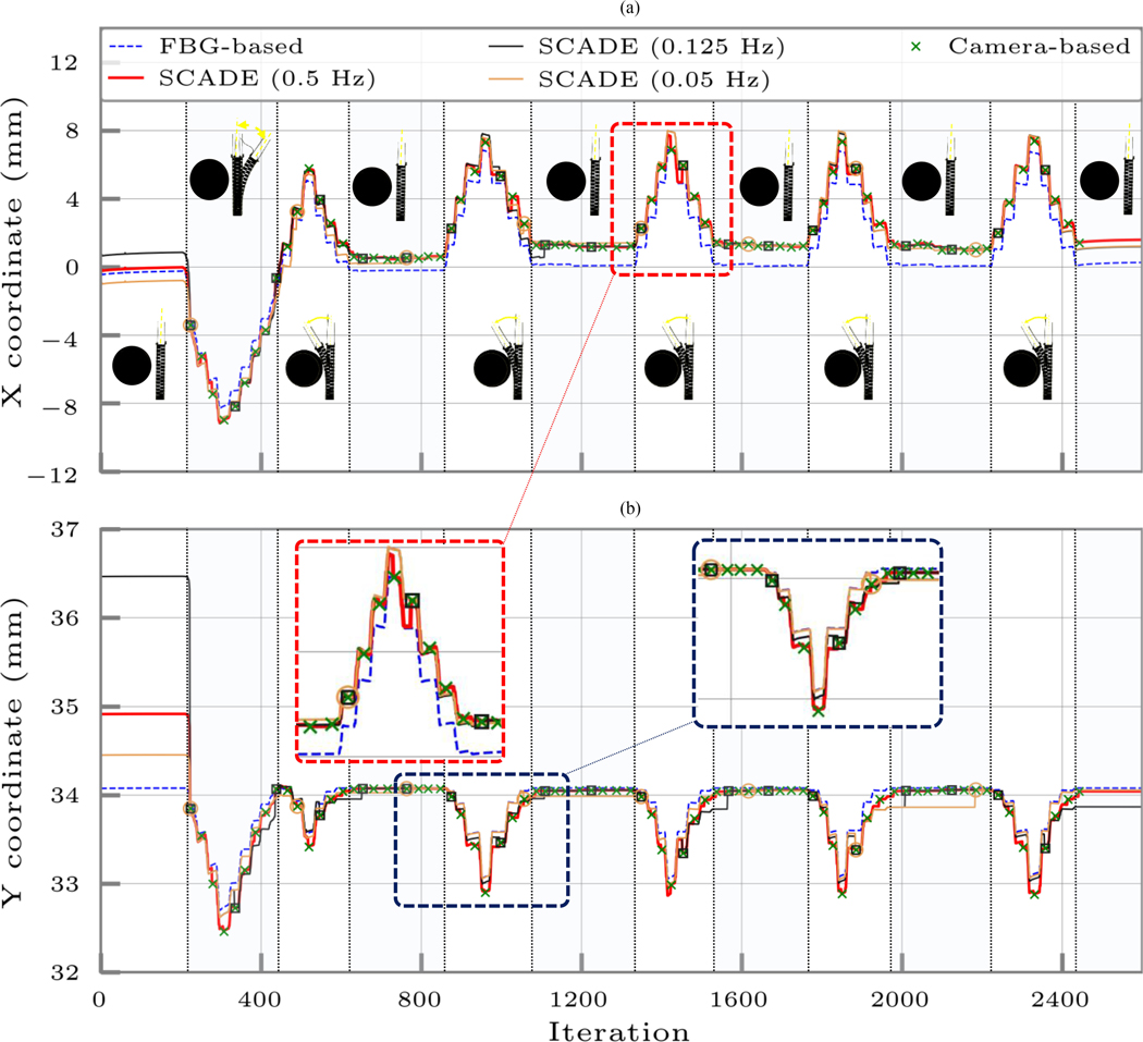
Fig. 8.
Ortho-snake’s estimated tip position (i.e., the X and Y coordinates) when its cables were antagonistically actuated with continuous displacement rates of 1 mm/s in an obstructed environment using 1) only the streamed FBG data and the online model-based reconstruction method described in Section III-B, 2) the instances of recorded and registered images by the camera, and 3) the SCADE algorithm performed with three different EIU imaging frequencies of 0.5, 0.125, and 0.05 Hz. The bending configurations of the CM have been shown in each cycle. The tip position is considered at the distal end point of the center line of the robot.

