FIGURE 5.

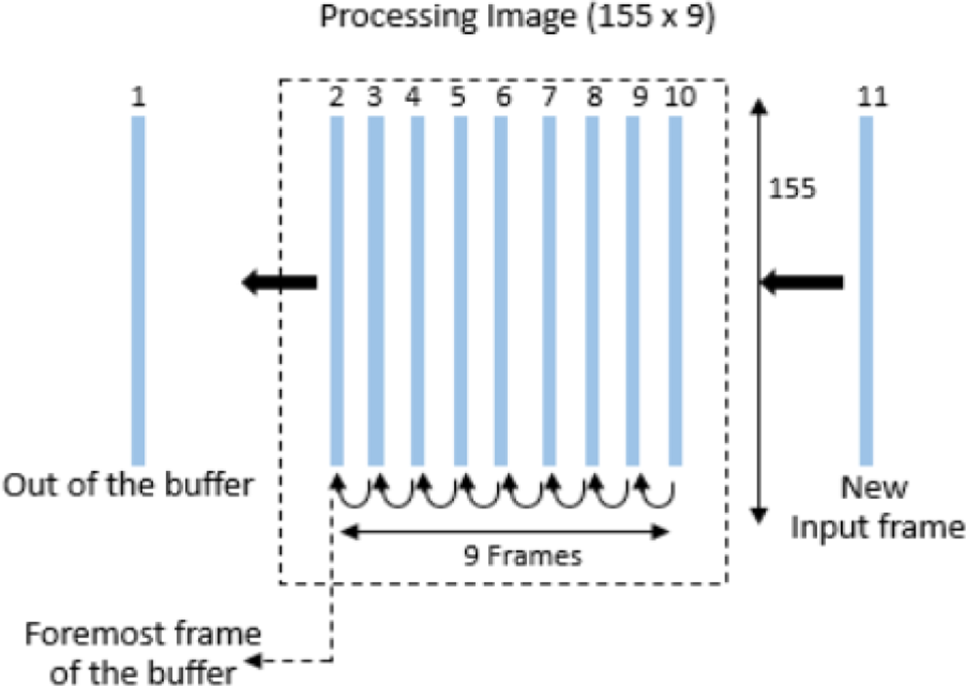
Buffer used to create input processing image. Here the frame 10 is the current processing frame. 2–9 are the preceding frames and 1 has left the buffer. When frame 11 comes in, frame 2 leaves the buffer.

Buffer used to create input processing image. Here the frame 10 is the current processing frame. 2–9 are the preceding frames and 1 has left the buffer. When frame 11 comes in, frame 2 leaves the buffer.