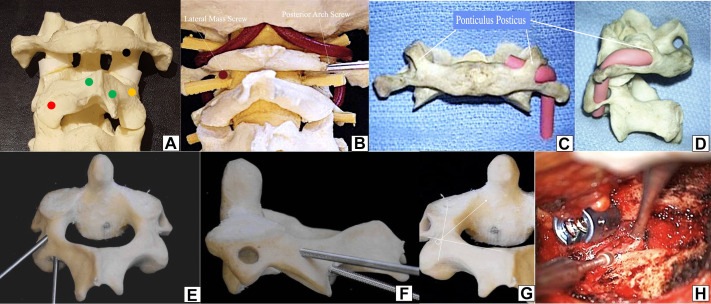
Figure 5.
(A) Sawbone model with a posterior view of C1-2-3. Black dot—entry point of C1 lateral mass screw—midportion of the lateral mass just below the inferior posterior C1 arch. Red dot—entry point of C2 pars screws and C2 transarticular screw—about 3 to 5 mm above the medial junction of C2-C3 facet joint, the medial position should not violate the medial portion of the spinal canal. Orange dot—entry point of C2 pedicle screw—transition between the lateral portion of the lateral mass of C2, a little inferior (2 mm) to the transition of the lateral mass-pars. Green dots—upper and inferior junction of the lamina-spinous process, which are entry points for laminar screws (crossing screws). (B) Sawbone model comparing the lateral mass screw entry point (left) with the entry point of posterior arch screw (right). (C) and (D) Posterior and lateral view of the ponticulis posticus—a thin thick bone covering the vertebral artery. (E) Posterior and (F) lateral comparative perspective of a C2 pedicle screw with a C2 pars screw—the entry point of the pedicle is above and lateral to the pars screw. (G) Illustrative direction of the C2 pedicle screw, with an intraoperative (H) picture of the entry point.

