
Figure 1.
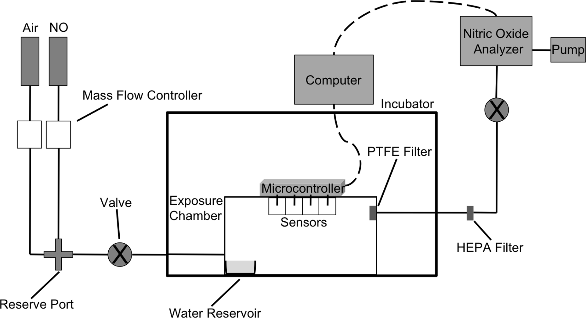
Schematic of gaseous NO exposure chamber. The flow rates of the gases were separately controlled to obtain precise concentrations of gNO. The combined mixture enters the humidified chamber through a single port while exiting through PTFE and HEPA filters to remove water vapor and aerosolized bacteria, respectively. The NO concentration of the output gas was analyzed using a chemiluminescence nitric oxide analyzer (NOA). The valves, connecting the gas cylinders to the exposure chamber and between the HEPA filter and NOA, allow for the creation of a closed, gas-tight system.