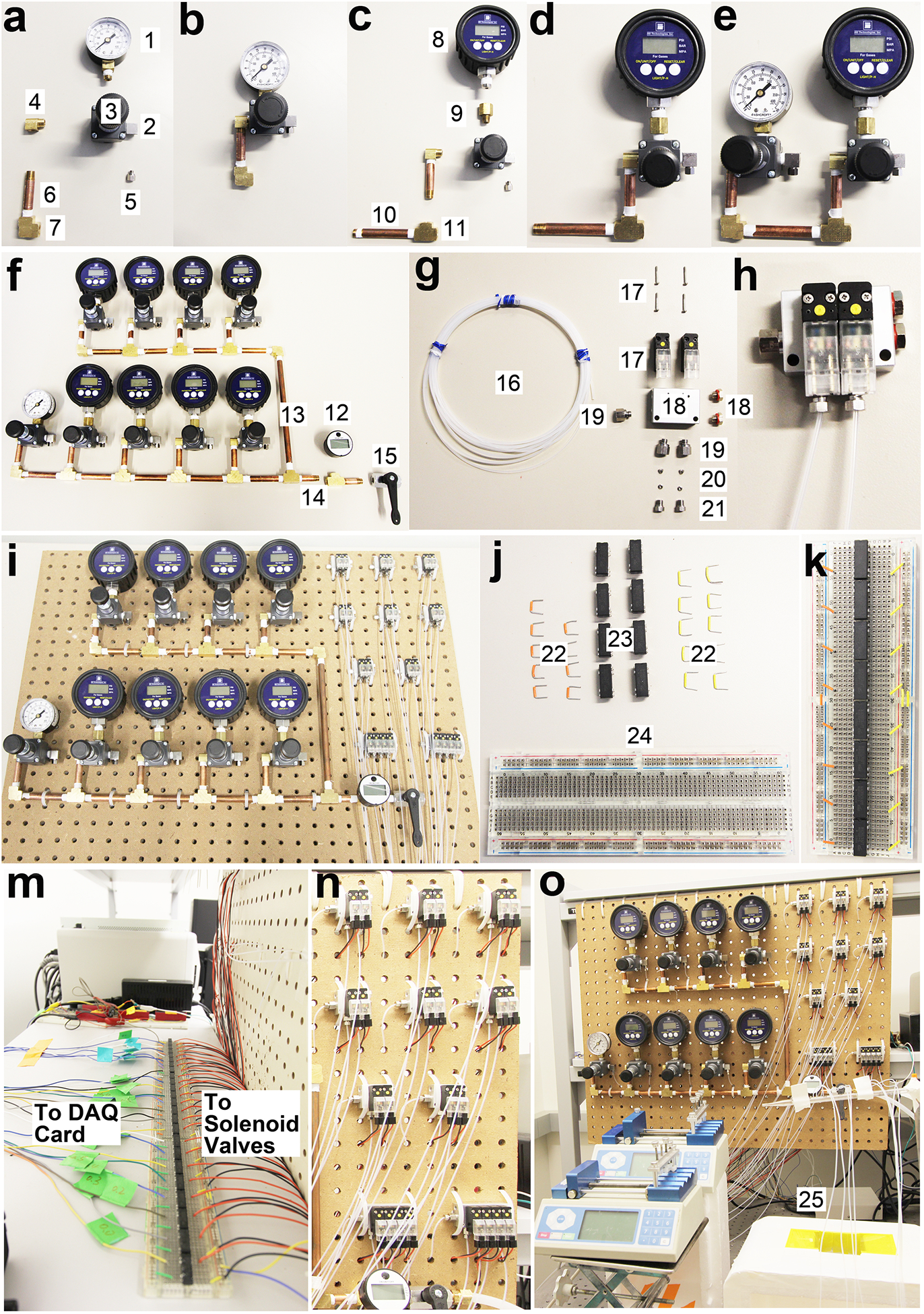
Figure 3 |.

The assembly of pneumatic control system for the 8-unit MOWChIP device shown in step-by-step fashion. All the individual parts are numbered and their information is listed in the “Equipment” list. (a-b) The assembling of a pressure gauge (#1), its associated pressure regulator (#3), and pipe (#6). (c-d) The assembling of a digital pressure gauge (#8), its associated pressure regulator, and pipes. (e-f) The assembling of all the pressure gauges and regulators. Gauge #1 and its associated regulator adjust pressure used in closing the sieve valves (at ~30 p.s.i.). 8 digital gauges (#8) and their associated regulators create pressure for oscillatory washing (at ~0.65 p.s.i.) in 8 units. The #12 gauge monitors the overall input pressure (90–100 p.s.i., from a pressured air source of the building in our case) which can be turned on or off by a ball valve (#15). (g-h) The assembling of parts associated with a 2-set solenoid valve. (i) Pressure gauges/regulators and solenoid valves are fixed to a pegboard. (j-m) Setting up reed relays on a breadboard for enabling control of solenoid valves by the DAQ card. (n-o) The assembled pneumatic control system. The inlets at the left of the solenoid valve manifolds (#19) are connected to the pressure regulators (#3) via PFA tubing.
