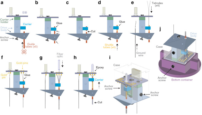
Figure 4.
Tetrode and fiber optic loading. (a) Side view of the DMCdrive. Start by moving the carrier to the bottom of the drive. Insert the five guide tubes (0.0120″/0.0140″, ID/OD) into the drive body. The configuration of the guide tubes is dictated by the desired arrangement of the tetrodes and the optical fiber (e.g., round or flat). (b) Glue (arrows) the guide tubes to the drive body and carrier. (c) Cut (arrow) the guide tubes between the drive body and the carrier. (d) Insert four shuttle tubes (0.0049″/0.0064″, ID/OD) into four of the guide tubes. The fifth guide tube will hold the optical fiber. Glue (arrow) the shuttle tubes to its respective guide tube. (e) Insert the ground wire, without insulation at the ends, into and through the drive body from below. Place one tetrode in each shuttle tube. (f) Secure the ground wire and the tetrodes to the EIB using gold pins. To enable movement of the tetrodes, glue (arrow) the tetrodes to its respective shuttle tube. (g) Insert the fiber optic (flat tip fiber: multimode, 200 µm core, 0.22–0.5 NA; ferrule: Ø1.25 mm, 6.4 mm long, Ø230 µm bore; Thorlabs) through the EIB into the empty guide tube. (h) Glue (arrow) the fiber optic to the EIB. Move the carrier up as far as possible. (i) Place the assembled drive in the case, and secure the drive to the case using two anchor screws (‘finished drive’). (j) For storage and transport of the drive, place the finished drive upside down in the bottom container and secure with anchor screws, and then place the top container over the drive. ID/OD inner/outer diameter.

