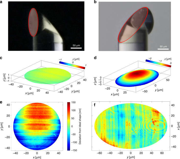
Fig. 2. Probe characterization.
a Microscope image of the probe with the flat front surface highlighted. b Microscope image of the probe with the curved TIR surface highlighted. c Confocal surface measurement result of the flat interface from a. d Confocal surface measurement result of a curved TIR mirror surface b. e Deviation from the ideal shape in the case of the flat surface. The RMS deviation for a beam footprint corresponding to an NA of 0.14 is 43 nm. f Deviation from the ideal shape in the case of the TIR surface. The RMS deviation for a beam footprint corresponding to an NA of 0.14 is 19 nm. The visible elliptical ring patterns are caused by the rasterization of the 3D printer within each printing layer and did not have a discernible impact on the optical performance

