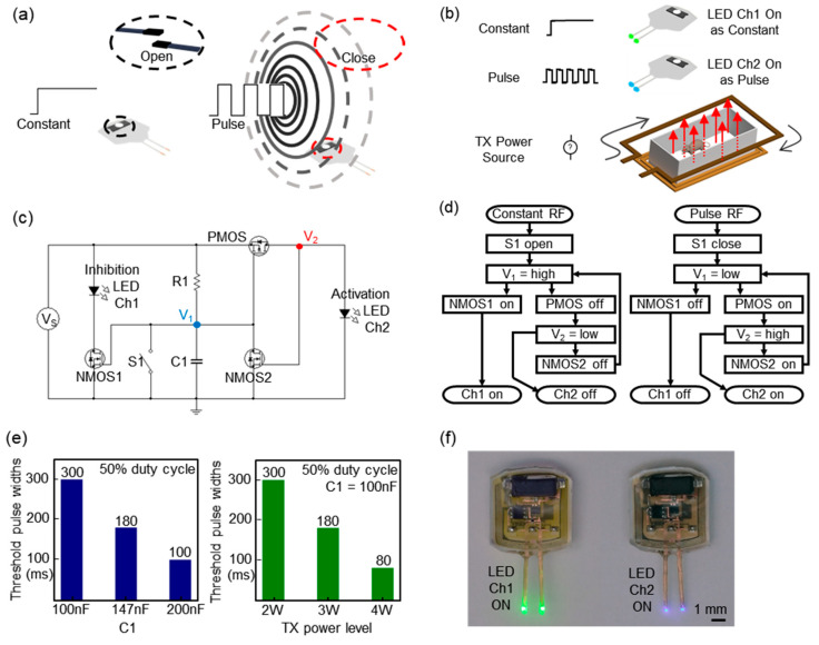
Figure 3.
Demonstration of an advanced operational mode and magnet-free operation to expand the function and its characteristics. (a) Illustration of a mechanism by which a train of pulse signals induces an alternating magnetic field. (b) Schematic illustration of a magnet-free operational mode: inhibition and stimulation of neural activity. (c) Circuit diagram of a dual channel device that offers an advanced magnet-free operational mode: inhibition and stimulation of neural activity. Here, a dual channel device automatically activates a channel in response to signals from a remotely located wireless TX system. R1 = 20 kΩ and the reed switch is denoted by S1. (d) Flowchart that depicts an actuation mechanism enabled by a pulse signal. (e) Plot of the measurements of the threshold pulse widths required for the switching operation as a function of a capacitor, C1, and TX power. (f) Pictures of an advanced operational mode and magnet-free operation.

