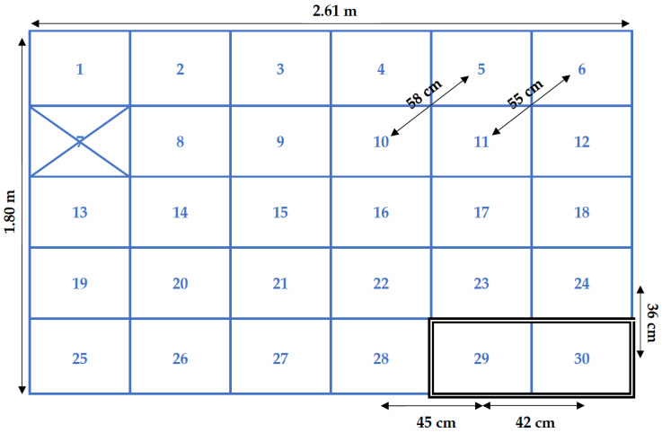
Figure 5.
Schematic top view of the RFID grid. One of the fifteen PVC antenna panels that includes two RFID antennas is outlined as an example (antenna 29 and 30). Distances between centre points of antennas are indicated, as well as the total size of the grid. The non-functioning antenna is marked with an X.

