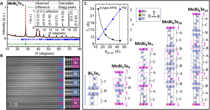
Fig. 1. Crystal structure of MnBi8Te13.

(A) Powder XRD and the refinement of MnBi8Te13. Inset: Low-angle (0 0 l) XRD peaks of the cleaved ab surface of MnBi8Te13. a.u., arbitrary units. (B) STEM images of MnBi8Te13 made on a focused-ion beam sample. The purple blocks label the [MnBi2Te4] SL, and the blue blocks mark the [Bi2Te3] QL. (C) Schematic drawing of the crystal and magnetic structure of MnBi2nTe3n+1 (n = 0, 1, 2, 3, and 4) with the stacking sequence listed. A, B, and C represent the bilayers of BiTe6 octahedra whose bottom Te atoms, center Bi atoms, and top Te atoms are on the cell edges, respectively. Magenta arrow, magnetic structure in the order state; blue block, edge-sharing BiTe6 octahedra; magenta block, edge-sharing MnTe6 octahedra, which are connected to the blue block via edge sharing. Inset: Tc (the critical temperatures) versus dMn-Mn (the interlayer distance between the adjacent Mn-Mn layers) and n versus dMn-Mn in MnBi2nTe3n+1 (n = 1, 2, 3, and 4).
