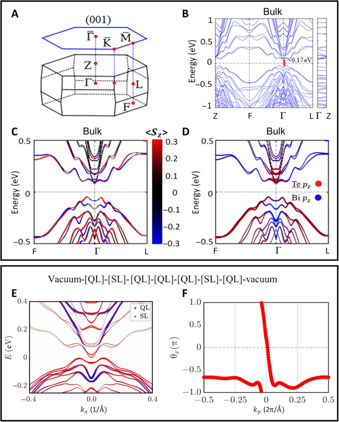
Fig. 5. DFT band structure of MnBi8Te13 calculated using the experimental lattice parameters with relaxed atomic positions.

(A to D) Bulk band structure. Bulk Brillouin zone (BZ) and the (001) surface BZ of MnBi8Te13 with the high symmetry points marked (A). Bulk band structure of MnBi8Te13 in the out-of-plane FM configuration, with spin-orbit coupling and correlation parameter U included (B). Spin-resolved band structure zoom in around the Γ point (C). Orbital-resolved band structure zoom in around the Γ point (D). The red and blue dots indicate Te pz and Bi pz orbitals, respectively. There are clear band inversions between the Te pz and Bi pz states at the Γ point. (E and F) DFT calculation of a seven-layered finite-sized slab model corresponding to the QL1 surface arrangement, i.e., with vacuum-[QL-SL-QL-QL-QL-SL-QL]-vacuum. (E) Band structure of this slab model. The sizes of the blue and red dots represent the fraction of electronic charge residing in the topmost QL and the nearest-neighboring SL, respectively. (F) Evolution of the sum of Wannier charge centers (WCCs) along ky in the kz = 0 plane. The trajectory of WCC is an open curve traversing the whole BZ once, indicating the Chern number C = 1 in the kz = 0 plane.
